Introduction
A Dynamixel is an off-the-shelf servo with integrated control that is controlled by commands over a digital interface. There are three protocols for such an interface: Modbus RTU, Dynamixel v1, and Dynamixel v2. We will only consider Dynamixel v2, which will be simply referred to as the Dynamixel protocol. However, before we do so, we must look at the lower-level electrical system.
This page provides an overview of the Dynamixel communication. It is not an exhaustive list of what is already in the Robotis manual but gives further insight into things left out of the manual, such as the low-level electrical side and some peculiarities. The Robotis manual should be read after the reader has read this page.
The target-audience is somewhat broad and can be anywhere between an experienced team-member wanting to cross-reference something, or a new member with some electrical or networking knowledge.
Universal Asynchronous Receiver-Transmitter
A universal asynchronous receiver-transmitter (UART) is an electrical device that sends data at an agreed upon bitrate or baudrate. Unlike Serial Peripheral Interface (SPI) and Inter-Integrated Circuit (I2C), there is no signal for the clock, and both devices on either end have to agree upon the common baudrate beforehand. It is common with UART to have to set a baudrate at the very beginning externally either by rewriting firmware or configuring a peripheral.
There is also a universal synchronous and asynchronous receiver-transmitter (USART) which is a device that can handle both synchronous and asynchronous communication and can more or less be used as a UART.
A UART has two pins, an input called RX, and an output called TX.
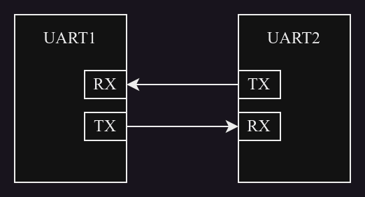
The term UART can also refer to the way how data is framed, thought informally almost as a very low-level and basic protocol. Here, UART can refer to the special bits that are needed to frame data, all of which need to be agreed upon between both devices on either end.

| Line | Logic-level | Description | Optional |
|---|---|---|---|
| Idle | 1 | is where there is no data. | no |
| Start-bit | 0 | is the beginning of the data. | no |
| Data-bits | ? | are the bits of data from the least significant to the most significant. | no |
| Parity-bits | ? | tell whether there has been any corruption of the data during transmission. | yes |
| Stop-bit | 1 | is the end of the data. | yes |
The receiver looks for the start-bit's falling edge. When it has found the edge, it begins to time and to sample each bit thenceforth based on the agreed upon bitrate. Most setups are written by three symbols, e.g. 8N1 means that there are eight data-bits, no parity bits, and one stop-bit. Both Dynamixel protocols and many other serial ones are 8N1. Henceforth in this guide, this is the assumed framing.
Two UARTs must agree on the baudrate, framing (e.g. 8N1), and the signal-levels in order to communicate.
Duplexity
Firstly, one must understand the concept of duplexity since the half duplexity of the Dynamixel protocol is not always intuitive for beginners. There are three kinds of digital communication, namely simplex, full duplex, and half duplex.
Simplexity is when data goes in only one direction, from Device-A to Device-B, where only the former transmits and only the latter receives. There is only one channel, and there may often be only one electrical signal. An analogy would be Alice giving instructions to Bob through a loud-speaker very far away.

Full duplexity is when data can go in both directions at the same time, between Device-A and Device-B. There are two channels, one for each direction. This is like having two simplex channels. There is no clash when both Device-A and Device-B send data at the same time since the two channels are separate. An analogy would be Alice and Bob writing letters or texting.

A pure UART will have two signals, RX and TX. RX is used for receiving signals and TX is used for transmitting signals. This is an example of full duplexity.
Half duplexity is when data can go in both directions, but not at the same time. There seem to be two channels but they are really combined into one. An analogy would be Alice and Bob talking to each other by walkie-talkies.

The Dynamixel protocol is half duplex; therefore, it is important to understand half duplexity and the needed flow-control and logic behind it.
The reader will soon see that the reason why the protocol is half duplex is the fewer number of wires - especially for RS485 - and the fact that servos only respond to instructions.
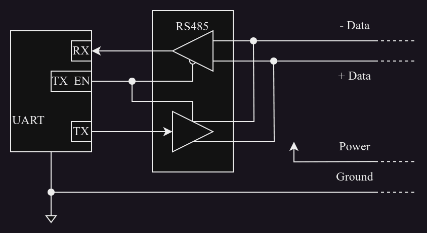
Often, a Dynamixel device's microcontroller has a UART to communicate on the bus. This UART has two pins, RX and TX. Therefore, in theory, it could be used for full duplexity. However, RX and TX get switched between by a transceiver, which is another chip on the board. The transceiver can switch between receiving and transmitting on the same bus-line. This transceiver has another input pin to set the direction, sometimes called the TX-enable or the direction.
Signal-levels
Pure UART often only refers to abstract bits or logic levels, not voltages. Signalling techniques such as RS485, RS232, and TTL are what are further needed for a complete system to define the electrical behaviour as well as the flow-control (e.g. RS232).
Transistor-Transistor-Logic
Transistor-Transistor-Logic (TTL) is a family of logical interfaces mainly for logical circuits. Its name refers to the transistors inside the chip used to control the voltage-level. It also refers to signal-levels for many UARTs and protocols. There are only three wires for a TTL setup for a servo, namely ground, power, and data. The NC7WZ241 chip is an example of a TTL transceiver that is found on the OpenCR.
Some Dynamixel servos use TTL, seen by their three-pinned headers. Such servos are still used on the Darwins in NUbots. Therefore, TTL is included in this guide.
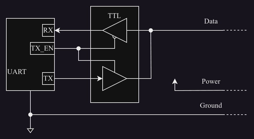
RS485
Transceiver
RS485 is an electrical standard that defines the signal-levels for many serial devices; it does not define a protocol but is instead used for many protocols. Unlike TTL, this has two wires for the data, here called positive and negative, but sometimes under different names such as either plus and minus or A and B. These two wires make up a differential signal. The THVD1550 chip is an example of an RS485 transceiver that is found on NUSense.
Differential Signal
In order to appreciate the power of such a differential signal, one must understand the challenges of noise and interference. For very long cables, the wires often behave like antennae and can thus pick up nearby interference from other electrical devices, especially from servos which tend to emit switching noise. As such, a big enough interference can flip a bit and lead to an error.
However, RS485 and other such techniques have an answer for this. Given a message , the transmitter sends a positive copy and a negative copy together as a pair. As long as the two physical wires are close together, any interference is both added such that the received positive signal is , and the received negative signal is . The receiver then subtracts the two, often with a difference amplifier, such that the interference is cancelled out, and the received message is .
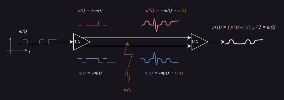
Indeed, this is a simple example as there is some more complexity in the way how the RS485 transceiver drives the signals, but this should give the reader the broad idea of how it works and to understand its advantage. Furthermore, this kind of interference is known as common-mode noise. As an aside, a differential pair cannot handle differential mode noise, which is however less common in our case. The reader can learn more about the two here.
It is important to understand the fact that there are two signals that make up a differential pair when probing the bus with either an oscilloscope or a digital-signal analyser - such as a Saleae. Often in such times, only one probed signal - ideally positive - is enough to see the data.
RS485 was historically used for communicating to automated machines on very long factory-floors with a lot of electromagnetic noise from machinery. Therefore, RS485 can deal with very long lengths up to a kilometre depending on the bandwidth. One may think that RS485 is overkill for such a small robot, but one should remember that servos can make a lot of electromagnetic noise because of their nature.
Twisted Pair
The robustness to interference is better when the two wires are twisted. This method is very common not only for RS485 but throughout telecommunications. When a pair of wires is untwisted, the area between the wires, although very small and thin, may make up a big enough loop that can pick up magnetic fields going through it. However, if the pair is twisted, then the big loop is now split up into smaller loops which are alternating in polarity such that the current induced across one small loop is cancelled out by that across the next small loop. Furthermore, a twisted pair is easier to manage and keeps the two wires close at all times.
Terminating Resistors
Further to RS485 are terminating resistors which are often important to minimise reflections and to maximise the received power. RS485 can only have two terminating resistors, best at either end of a bus. However, RS485 doesn't always need two terminating resistors in order to work, but it is best to have them for the best performance. Nearly always, the terminating resistor is 120 Ω. The reader can learn more here.
v2 Protocol
Asymmetry
The Dynamixel v2 protocol is a basic serial protocol much like Modbus. The most important thing to understand is that the Dynamixel protocol is fundamentally asymmetric and works with two classes, a controller and a device, analoguous to SPI, I2C, and Modbus for example. The controller only sends an instruction or a request, only to which a device responds with a status or a response. Robotis specifically use the terminology of 'instruction' and 'status' in their documentation, but the reader may also see 'request' and 'response' in other places. Only the controller can initiate an instruction-status exchange. There can be many devices - at most 253 -, but to avoid collisions, there can only be one controller on a bus at a time. One must remember this when connecting the Dynamixel wizard externally to a robot while it is running.
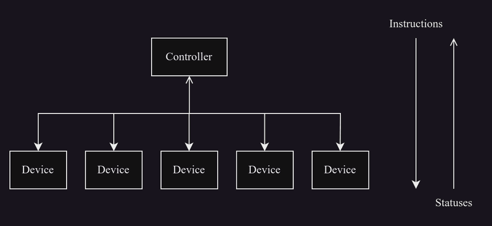
In our case, the controller is a subcontroller, e.g. NUSense, CM740, and the devices are often servos, but in some cases other peripherals such as the NUFSR.
Although it is often called a subcontroller, the OpenCR is not a controller but rather another device - often with an ID of 200 - that responds to instructions with IMU data. In this setup, the controller is actually the USB serial-converter.
Packets
An instruction-packet is made up such:
| Field | Length | Bytes | Brief |
|---|---|---|---|
| Header | 4 | 0x00FDFFFF | The start of the packet. |
| ID | 1 | ? | The ID of the receiving device |
| Length | 2 | ? | The length of the packet starting from the instruction, i.e. length = N + 3. |
| Instruction | 1 | ? | The kind of instruction |
| Payload | N | ? | The parameters relating to the instruction if any. |
| CRC | 2 | ? | The error-checking for the receiving device. |
A status-packet is made up such:
| Field | Length | Bytes | Brief |
|---|---|---|---|
| Header | 4 | 0x00FDFFFF | The start of the packet. |
| ID | 1 | ? | The ID of the responding device |
| Length | 2 | ? | The length of the packet starting from the instruction, i.e. length = N + 4. |
| Instruction | 1 | 0x55 | The sign of a status. |
| Error | 1 | ? | The error if any. |
| Payload | N | ? | The returned data relating to the instruction if any. |
| CRC | 2 | ? | The error-checking for the receiving controller. |
The data is in little-endian format.
Cyclic Redundancy Check
The cyclic redundancy check (CRC) is a value that is appended at the end. It helps tell whether there has been any corruption in the received packet. Firstly, the sender computes the CRC of the whole packet soon to be sent - excluding the CRC of course - and appends it on the end. When the receiver has received this packet, it computes its own version of the CRC and compares it to the appended CRC. If the two CRCs are different, then there has been an error. One can learn more here about how the CRC works mathematically.
There are different ways to calculate the CRC depending on the polynomial. The Dynamixel protocol uses CRC-16-IBM which has as the polynomial, otherwise wrtten as 0x8005. An algorithm for the specific CRC that the Dynamixel protocol uses as well as a look-up-table can be found here.
Error
One difference between an instruction-packet and a status-packet is the extra error-field in the latter as well as the fixed instruction-field of 0x55. Firstly, if the most significant bit of the error-field is 1, then there has been a hardware problem; reading the hardware-error-status in the device can give more details. The rest of the bits can tell the following.
| Value | Error | Brief |
|---|---|---|
| 0x01 | Result Fail | Failed to process the received instruction-packet. |
| 0x02 | Instruction Error | Either an undefined instruction has been received or an action has been received without a reg-write. |
| 0x03 | CRC Error | The computed CRC does not match the received one. Likely, the instruction-packet has been corrupted or the original CRC is incorrect. |
| 0x04 | Data Range Error | Data to be written is outside the allowed range. |
| 0x05 | Data Length Error | Data to be written is shorter than the addressed field. For example, only two bytes are written to a four-byte field. |
| 0x06 | Data Limit Error | Data to be written is outside the limit that is set in the ROM. |
| 0x07 | Access Error | Attempted to write to an either read-only or an undefined address; attempted to read from an either write-only or undefined address; attempted to write to the ROM whilst the torque is enabled. |
Control-Table
Before we go further, some context may be needed for the protocol and how it is used as a means to an end. The Dynamixel servos have their own integrated control with a closed-loop, feedforward gains, etc. Therefore, one controls the servo by giving a target, often the angular position of the shaft. Such data can be written to and read from a unified control-table which is a block of memory that is accessable by the Dynamixel protocol. For example, the two most common registers to access are the goal-position and the present position; the former is written as a target for the servo; the latter is read as the actual position. One can look at the control-table for the XH540-W270 as an example.
Instructions
The controller can send a variety of instructions to either write to and read from these registers as well as to control the servo as a whole. The Dynamixel v2 manual has a full overview of the different instructions. However here, we will only look at the most common ones that are used at NUbots.
Ping, 0x01
Pings either a device with the given ID or all devices if the ID is 0xFE which is the broadcast ID. The instruction-packet has no payload; so, the length is always 3. The status-packet has a payload of three bytes, namely a half word for the model-number and a byte for the firmware-version. If the broadcast ID is set, then all devices on the bus send status-packets in order of their IDs.
The instruction-packet:
| Field | Length | Bytes |
|---|---|---|
| Header | 4 | 0x00FDFFFF |
| ID | 1 | ? |
| Length | 2 | 0x03 |
| Instruction | 1 | 0x01 |
| CRC | 2 | ? |
The status-packet:
| Field | Length | Bytes |
|---|---|---|
| Header | 4 | 0x00FDFFFF |
| ID | 1 | ? |
| Length | 2 | 0x07 |
| Instruction | 1 | 0x55 |
| Error | 1 | ? |
| Model-number | 2 | ? |
| Firmware-version | 1 | ? |
| CRC | 2 | ? |
Read, 0x02
Reads data from the device's control-table. The instruction's payload is the starting address in the table to read from which and the length of data, both as half words. The status' payload is the requested data from the servo's control-table; therefore, the packet-length is variable.
The instruction-packet:
| Field | Length | Bytes |
|---|---|---|
| Header | 4 | 0x00FDFFFF |
| ID | 1 | ? |
| Length | 2 | 0x07 |
| Instruction | 1 | 0x02 |
| Starting Address | 2 | ? |
| Data-length | 2 | X |
| CRC | 2 | ? |
The status-packet:
| Field | Length | Bytes |
|---|---|---|
| Header | 4 | 0x00FDFFFF |
| ID | 1 | ? |
| Length | 2 | X + 4 |
| Instruction | 1 | 0x55 |
| Error | 1 | ? |
| Payload | X | ? |
| CRC | 2 | ? |
The status-packet's length is variable given how much data is requested in the original instruction. Therefore, the controller's firmware has to infer the length from how much data it had just requested.
Write, 0x03
Writes data to the device's control-table. The instruction's payload is at first the starting address in the table to write to which as a half word. Then, the rest is the stream of data to write. The status has no payload.
The instruction-packet:
| Field | Length | Bytes |
|---|---|---|
| Header | 4 | 0x00FDFFFF |
| ID | 1 | ? |
| Length | 2 | X + 5 |
| Instruction | 1 | 0x03 |
| Starting Address | 2 | ? |
| Data | X | ? |
| CRC | 2 | ? |
The status-packet:
| Field | Length | Bytes |
|---|---|---|
| Header | 4 | 0x00FDFFFF |
| ID | 1 | ? |
| Length | 2 | 0x04 |
| Instruction | 1 | 0x55 |
| Error | 1 | ? |
| CRC | 2 | ? |
The instruction-packet's length is variable given how much data is written in the original instruction. However, unlike that for the read-instruction, the device's firmware cannot expect what the length is and can only infer it from the length-field in the packet. Therefore, when one writes firmware for a device, one must consider how to parse a write-instruction of unknown length.
SyncRead, 0x82
Reads data from multiple devices' control-tables. The instruction's payload is at first the starting address in the table to read from which and the length of data, both as half words. Then, the rest are a list of IDs of the servos to read from which.
In response, all devices requested send their status-packets in order of ID. Like before with a read-instruction, each status' payload is the requested data from the device's control-table.
The instruction-packet:
| Field | Length | Bytes |
|---|---|---|
| Header | 4 | 0x00FDFFFF |
| ID | 1 | ? |
| Length | 2 | N + 7 |
| Instruction | 1 | 0x82 |
| Starting Address | 2 | ? |
| Data-length | 2 | X |
| List of IDs | N | ? |
| CRC | 2 | ? |
The status-packet:
| Field | Length | Bytes |
|---|---|---|
| Header | 4 | 0x00FDFFFF |
| ID | 1 | ? |
| Length | 2 | X + 4 |
| Instruction | 1 | 0x55 |
| Error | 1 | ? |
| Payload | X | ? |
| CRC | 2 | ? |
Both the instruction's packet-length and the statuses' packet-lengths are variable. Not only that, but a device has to wait for other devices with lesser IDs to send their status-packets before it. Therefore, when one writes firmware for a device, one must consider the timing of other requested devices.
SyncWrite, 0x83
Writes data to multiple devices' control-tables. The instruction's payload is at first the starting address in the table to write to which and the length of data, both as half words. Then, the rest are blocks where each block begins with an ID and the data to be written.
The written devices do not send statuses, even if their status-return-levels are set to all.
The instruction-packet:
| Field | Length | Bytes |
|---|---|---|
| Header | 4 | 0x00FDFFFF |
| ID | 1 | ? |
| Length | 2 | 7 + N(X+1) |
| Instruction | 1 | 0x83 |
| Starting Address | 2 | ? |
| Data-length | 2 | X |
| ID, first device | 1 | ? |
| Payload, first device | X | ? |
| ... | ||
| ID, N-th device | 1 | ? |
| Payload, N-th device | X | ? |
| CRC | 2 | ? |

